

Call me Emma
An orbituary to a nice lady
Hi, my name is MAN 630 L2AE. Friends are just calling me Emma. I was born after the war in the late 1950’s. I had my first rollout in 1957. It’s looked so funny, that one year later the young German “Bundeswehr” brought me into service. I was the successor of the M4500A and I worked here for more than 40 years. After my retirement I found a lot of fans, one of the reasons was my tough characteristics. You will not find any power steering or synchronized gearbox. But I will start up, without any problem after many long years of silence. My multifuel engine takes anything he has got. The most important thing is, it must burn, and that’s all. The best for me is Diesel, from this fuel I can do 30 L / 100km on asphalt road and I can run at an unbelievable 67 km/h.
Off road it’s could be maximum 38 km/h and I can tow 6 tons as my name says. However when I worked I was only allowed to tow 5 tons. The 30 is because of the 130 HP of my D 1246 MV A engine.
To make it complete: L: Lastkraftwagen, the German word for Truck/Lorry.
2: is the model series
A: Allrad, the German word for all wheel drive
E: Einzelbereift, German word of single tires.
But keep it simple: just call me Emma.
The most of us will not have the money to follow this offer and buy an original Emma. For us the German model company robbe offer a 1:12 semi scale model of this nice lady.
So the test started with the delivery of the nice coloured carton of Emma one day before Father’s Day. I was a little bit surprised by the weight of the carton. My first encounter at the exhibition in Sinsheim the model didn’t feel so heavy.
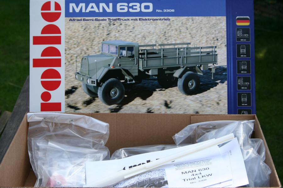
After opening the carton you will find a lot of air. To protect the contents some plastic airbags are included. All small parts are packed separately into bags, which are fixed to the carton. This protects all the part during transport. The main parts, which will make the model Emma, are placed deep in the protective packaging. Here are the sheets, which are the holder for the milled parts. My first idea was: phew, this is lot of work. The next idea was: nice work, good job.
Totally eight sheets of PS with the milled parts of the cabin and the flat are waiting. The angular design of the cab simplifies the building this model from these parts. The model builder will find a black and white instruction in four languages and shows all sheets as numbered. The sheets themselves are not numbered, to identify each sheet place it on 1;1 diagram in the instruction manual. If the manual is damaged during the building of the truck, you can download a new one from www.robbe.de as pdf.
The first area of the manual is well known from the robbe Mountaineer. The Mounty was released in spring 2006 and this truck used the axles, which are well known from the famous robbe Panther Airfield fire engine. The drive train is technically 10 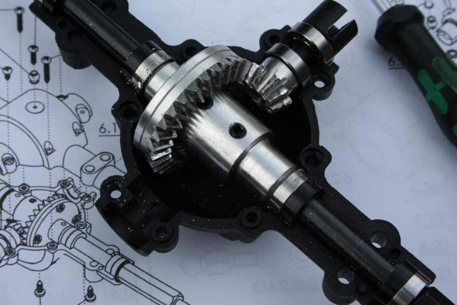
years old, so it wasn’t the first time for me to set up the axles, I decided to start at job in the garden. Nice model, nice weather, cold drink, I couldn’t be more happy?
The frame of the MAN 630 is one u-profile differs to the frame of the robbe Mountaineer, which are two-parts. This u-profile is covered by foil which must be removed before starting to build. All the pressings are cut very cleanly with no burs to be found.
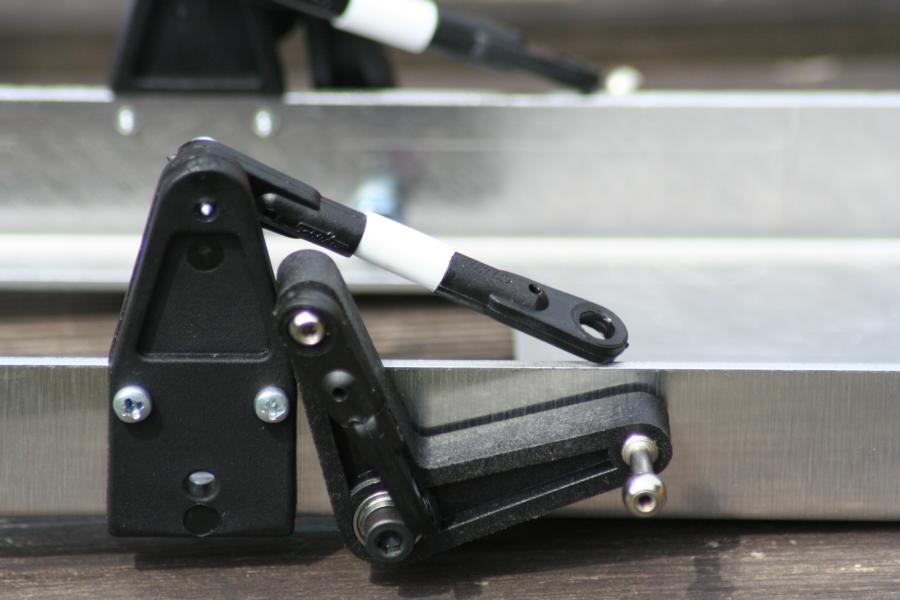
One special of the suspension are the horizontal dampers, are the first to be installed. Two ball bearings per lever assure less friction at the pivot point. Step 2 are tension struts in the lower linkage to the axles. The distance should be fixed to 9 – 10 mm. I cut four lengths from plastic tube to insure exactly the same distance. The second advantage of these tubes, is to give a smooth surface to stop stones getting stuck.
I was a little bit confused by step 2 in that robbe use M3 SHCS near to M3 slotted screws. Both are work, but it would be better if you could use only one tool.
The self-tapping screws to fix the pivot points also have a well-known problem. The tips of the screws inside the frame and can catch your fingers. Nothing really fatal, but still it hurts.
While assembling the suspension strut an error stands out, one spring plate was made with the wrong diameter of bore. But this mistake could be fixed very fast by drilling it out to the right dimension. Up to this point all bags were filled in correct way. Simply rule: new construction section, new bag. This is a clear instruction, so the first three steps were completed without any problems.
The next step is to fix the motor. The standard silver can motor is not the strongest, so gears reduce the speed and increase the torque. The motor is connected to the intermediate gearbox by bolts to a CNC milled alum-part, which looks very nice and professional. This holder is fixed to the frame by sheet-metal screws. I would prefer if here were M3 screws. The sheet-metals screws fix it, but do not look not so nice.
The transfer case is also an old well known part, it’s a dinosaur of robbe transmission technique!
Two ball bearings and two sintered bearings offer play free running. The small brass gearwheel runs smooth on the plastic gearwheel. To build this transfer case needs no discussion as it is an easy stage. A lexan cover keeps the mud and dust out from the gearwheels, secured by two screws at the bottom of the cover. I prefer to fix it by four screws on the top, so the bottom of the r gearbox is smooth and cannot catch on rock or stones.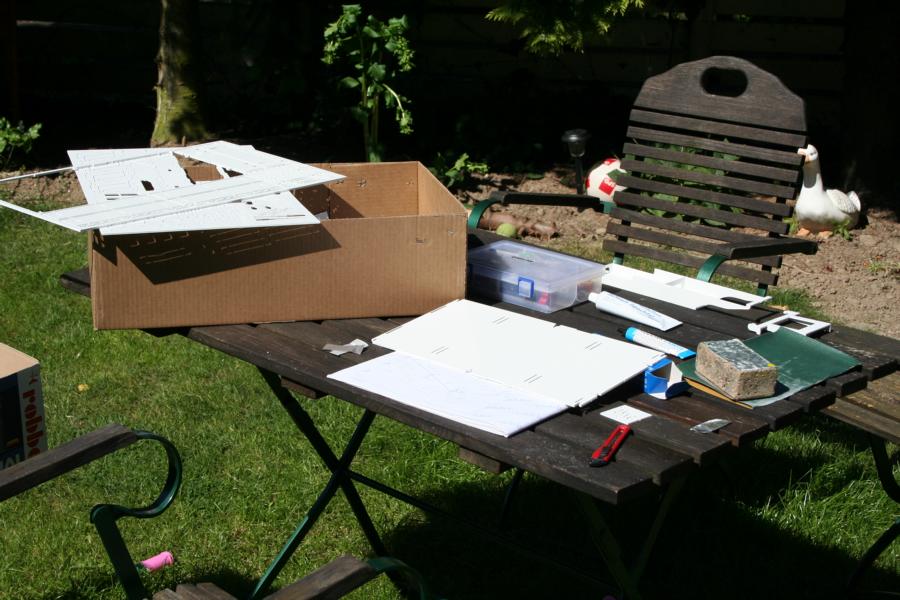
The axles are the next step: Good old fellows these axles, know from the beginning of robbe truck producing. The most important parts are done in aluminum. The beveled gearwheels must come together and run smoothly. In the beginning this was really hard working. The teeth of the gearwheels in the rear axle caught on each other, so it took a long time with a drilling machine and a lot of oil to get the axles running smoothly.
I started with the steering axle and here the beveled gearwheels went together like clockwork. This compensated for the stress with the rear axle. All axles are set up with ball bearings. In the axle casings the ball bearings are not sealed, so dust, water and other dirt will work in and reduce the bearing life. Closed ball bearings would have been a better alternative.
The steering is working by a micro servo, which is fixed in a special frame directly onto the axle. So suspension can work without any influence to the steering. The frame was deformed a little bit by fixing the servo, because the screws must find their way in the aluminum. The 3,7kg force servo is not the strongest for a truck which will mostly running off-road. Rigid through-drive, fat tires and heavy terrain took their toll. A component for mounting a standard-sized servo would be desirable.
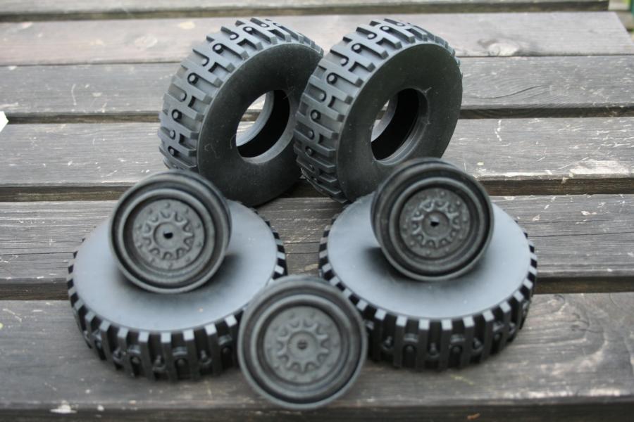
Talking about the tires, I'm not a fan of these tires as they are too hard, they are not as soft as the ones fitted to the Mountaineer. Profile is not scale and therefore does not suit the looks and finish of the MAN. The experience from the Mountaineer shows that the tread profile quickly fill with dirt and mud and is reluctantly clear again. But the rims are nicely detailed. The instructions suggest filling the tire with lead, to lower vehicle the center of gravity and increase ground pressure and traction. This is indeed true, however it can also increase wear on the drive train, as it will increases the tire scrub caused by the lock differentials. Here, moderation is the key so do not overdo it. Man buys only rarely an advantage without a disadvantage.
Interim conclusion:
The chassis, which is now compete, brings old acquaintances with old advantages and old disadvantages. These techniques have proven successful in recent years, with some of the ancestors of the MAN 630: Panther and Mountaineer show that the technology works. Worn parts are easily available and quickly replaced.
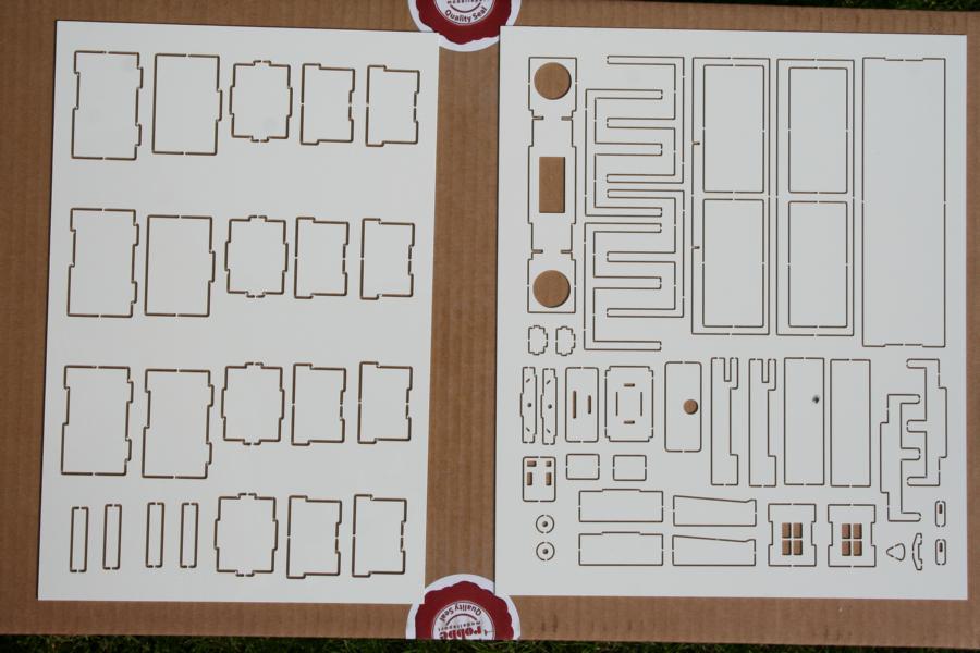 As mentioned above the MAN 630 is located deep in the box in the form of eight plastic sheets. The components are machined from different thicknesses of plastic sheets. Only short joints hold the parts in place. For ease of handling are two DINA3 prints to 1:1 scale at the box, shows the eight boards with their parts.
Here is the numbering of the parts as there are no markings on the plastic parts.
Screwdriver and long-nosed pliers are placed back to the toolbox as now we need knife, glue and sandpaper.
Starting with the battery box and the rear body.
These first parts showed, the need putty to get a smooth finish, as the slots and long holes fit together well but leave clearly visible holes. The finished parts can be stored on the frame.
The MAN 630 is designed as flatbed truck with drop down side. The next step is to attach the sides and the hinges that hold the side boards. In retrospect I would have built up the side boards first and used them to adjust the alignment of the hinges. The assembling of the first side board took a little time more, because the manual wasn´t clear. To me the manual was confusing in this part and I look forward in the manual being made clearer. Here the side boards are shown in finished.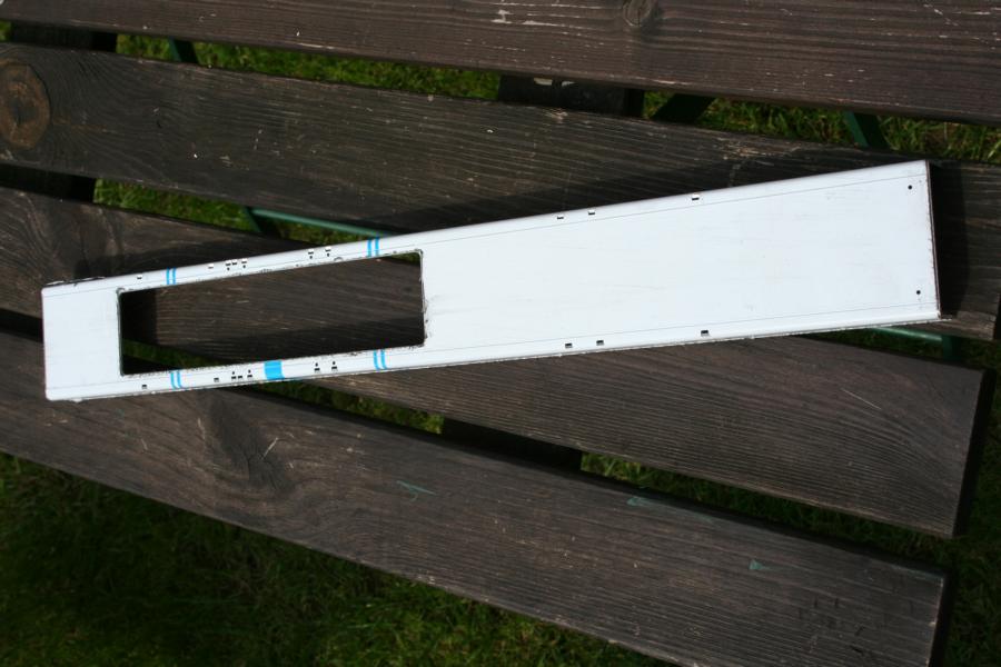
The ABS-stripes of the sides are cut on the buzz saw. A knife couldn´t cut this plastic. Two pairs of side boards are built in this way the only difference is the direction of the planks. The side boards are ready to install. Now the front- and tail- gate had to be built. The front gate is easy going. The tail gate can be opened and has two stepladders which are fold-away. The step treads now need to be drilled. In a 3 mm square we need a hole of 1,5 mm. If this is done correctly we will have 0.75 mm on each side. If this is not correct, the ladder will be shorter! The ladder of Emma is in original length.
After the sides are mounted on the hinges with screws, the rear of the truck is nearly complete, but it is still not yet a MAN. At this time every truck can happen.
Two special items should be fitted to the rear, the back lights are made from aluminum. The plastic parts fitted without any adjustment. You only need to place the LEDs inside. The second part is the cat’s eye placed on a plastic strip on each side. These strips will break off while driving off-road. So I changed the plastic to rubber.
So with great strides we are at last approaching the cab. To illustrate the final form and as an aid to assembly, a completed model is printed as an introduction to this phase of construction.
 The Instruction allows the modeler easy start into the body. The side panels with the door are assembled at the first. Caution should be exercised when comparing the real parts to the 1:1 diagram in the manual. Some of the parts do not quite match the exact dimensions of the diagram, this is only a matter of a few millimeters, but care must be taken in selecting the correct parts for each stage of construction. Thesameappliestothedoors. The stiffening strips measure really better and not by applying the schematic determine. Even for these components must be primed and sanded. So thebodygrows soslowlyin three dimensions.
Please keep an eye on the manual and the written instructions to insure the parts are assembled in the correct order, otherwise some components are in way of ones to be fitted. The assembly of the dashboard is only mentioned because I think it is a pity that there is not a decal with the instruments. On the internet I have only found inadequate images of the originals, so the only the solution remains with the brush. Evenashiftand brake leverswould be nice, but this can easily be created. So slowly it looks like a real truck, only the hood is missing. The front with their (real) metal lattice is delicate.
Theoutergroove facingarereally setonedge. The plastic around the edge is paper thin, so stick it together first and then sand everything, everything works smoothly. There are significant edges to alien and finish here, but nothing that could not be fixed with sandpaper. The above-mentioned metal grid I would install until after the final painting, as it is to remain metallic silver. The next step is to glue the bumper of the Emma and she looks nearly ready. Fitted in the bumpers are the headlights of aluminum, these can have working lights. As lenses are fixed exactly in the socket it may be difficult to remove later without damage to install working lights, so it is therefore advisable to mount the LED lamps before finishing this stage.
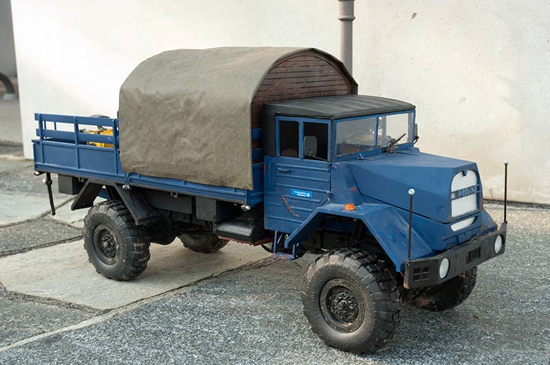
 Everything has fitted together and the MAN 630 Semi Scale Trial Truck has slowly but surely appeared before you. The doors and the bonnet are attached with hinges and screws to the rest of the body, which allowsthesepartsto open and close. Still the roof is missing from the 630 and just like the origin stands as a convertible car. The roof is put on the model but cannot be folded. Now Emma is standing in maiden white on the sitting room table.
This gave me the idea that the original trucks were use by the Red-Cross and German Federal Agency for Technical Relief. So the color was clear, the truck must become blue, but not brilliant fresh from the factory blue, but rusty and used befitting of her age. The painting was done by aerosol can in matt finished black and blue. Some rusty parts were placed. These rusty spots were colored first in brown and then painted a mixture of water, salt and sugar. After drying these areas were colored again.
After the color was dried the salt and sugar can be removed by water. Brown color of rust and the grey of prime coat are dropped behind. Inside the cabin a gearshift and brake lever were made from wire.
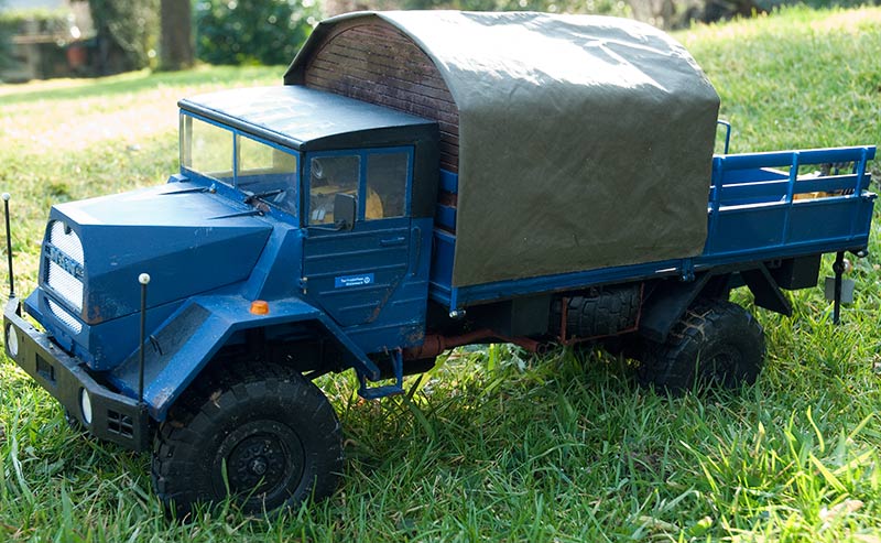
So she can run outside in the model world Radio control must be fitted:
The receiver and the ESC were placed under the engine hood, the battery is placed under the flat bed. The battery can stay in place during charging, but I wouldn´t recommend this as the battery may increase in temperature during charging and could damage battery and truck.
Emma is running really quietly. The steering could have more power and also the steering lock should tighter. Maximum speed of little Emma is really good, 5 – 6 km/h in 1:12 is nearly original speed of 67
Conclusion:
To build the truck and driving was very funny. It was exciting to bring the truck on the wheels, even the exactness of the single milled parts could only corrected with filler and sandpaper. The MAN 630 can be build easy at the kitchen desk. There is no need of special tools. To name little Emma a TRIAL Truck is more commercial than reality. She is running well off road, but only she has enough space around her. The wonderful parts under her flat are hindering the way forward in stony ground. A competition truck Emma will never be, but a really good truck for the garden, the building site or the forest.
- This article was written after I got this lady to build. I found the article on my PC after we restored our webside.